Perhaps an even greater challenge is posed by very complex objects, composed of hundred of thousands (if not millions) of primitives. Such models are not uncommon since the advent of 3D scanning technology, and any robust commercial lighting simulator should accommodate that type of complexity. Therefore, we oriented our research towards the hierarchical simulation of such objects on two fronts; a multi-resolution approach, and a stochastic approach.
Willmott and Heckbert [WH00] have proposed to build multi-resolution models with "face clusters", which are then directly inserted into the radiosity algorithm. Their approach works well for connected polyhedra and allows very significant speedups. We have approached the difficult issue of arbitrary models that cannot be readily simplified using face clusters, and investigated how to provide a simplified representation that is “radiometrically equivalent”. Such a representation can then be inserted into the scene to replace the complex geometry, and a simplified radiosity solution can be computed. This will, in time, be combined with the instantiation work described in [SS00], since the global solution obtained from the simplified representation can then be used to "zoom in" on the replaced objects.
Our approach for constructing radiometrically equivalent objects consists of first computing the "phase function" of a candidate cluster that we want to simplify. This can be done either by computing lighting solutions for this cluster subjected to directional illumination from a number of directions [SS00], or more simply it can be approximated by considering the visible projected area in all incoming and outgoing directions, taking into account the correlation between these directions. An example of such a function is shown below (Figure 3), computed for a 10,000 polygon model (we show the shape of the reflected radiance function for the white incident direction, but the actual phase function is 4D and essentially represents such a radiance function for ALL possible incoming directions).
Once this phase function is computed, we launch an optimisation process that selects a (hopefully small) number of polygons, which, when taken together, respond to light in a similar manner. This new structur is called avatar. In the example used, the set of polygons comprise 74 polygons (Figure 3-1d/3-2d). Its phase function is indicated in different modes (wire frame or filled) in Figure 3-1abc/2abc. Note how it closely approximates the true phase function, for a fraction of the number of polygons.
Although several questions remain open (such as visibility determination using simplified clusters), these result are extremely promising and open great opportunities for the simulation of very large scenes.
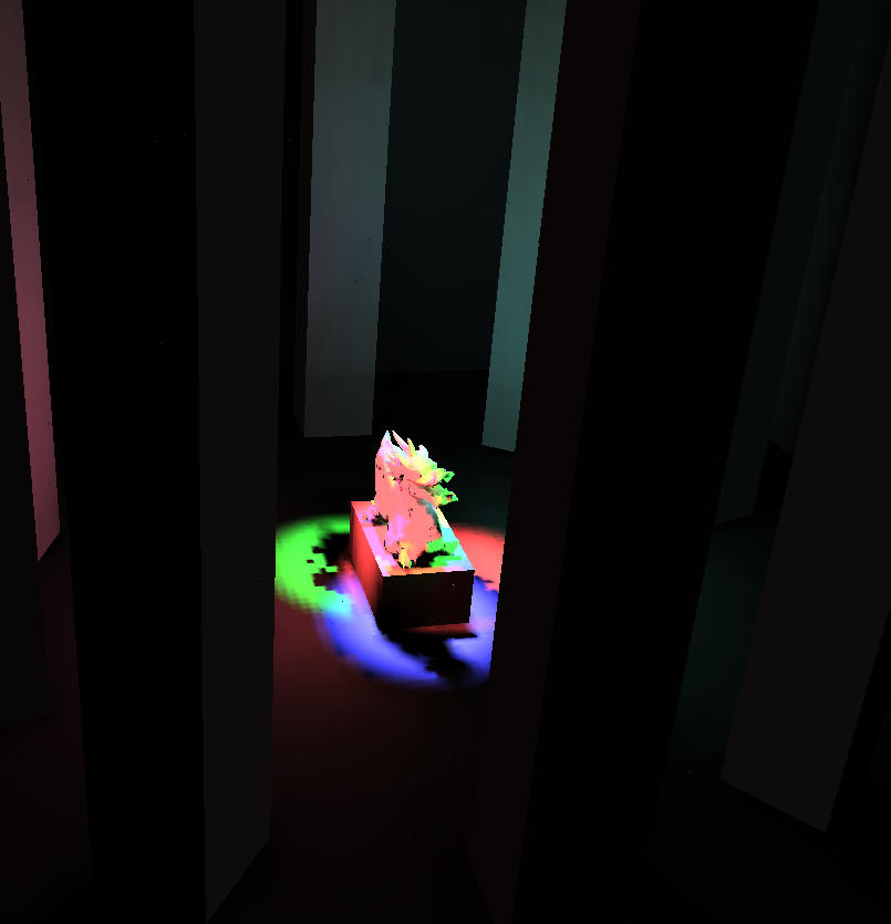
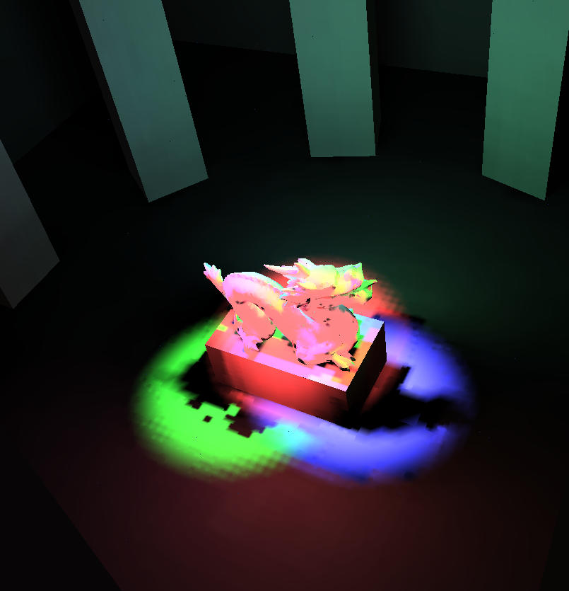
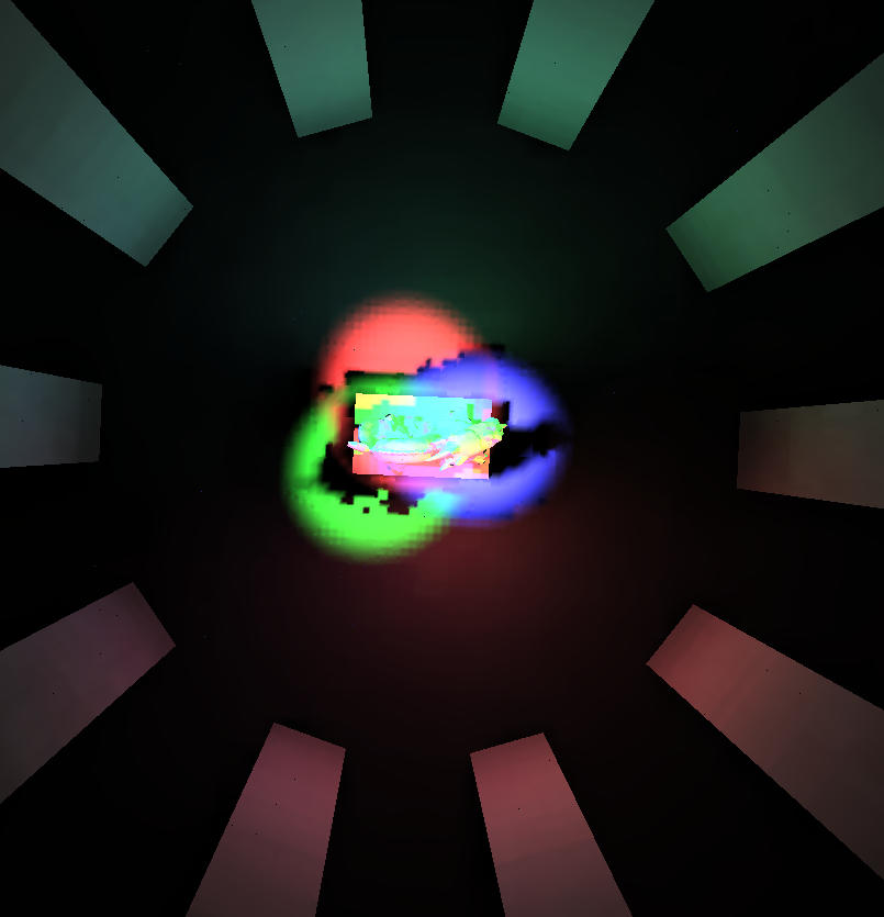
The test scene is composed by a dragon (10.000 polygons) and three spot lights of different colors (red, green and blue) as you could see in figure 1.
Figure 1: Test scene composed by a dragon and three spot lights (in yellow)
|
Solution with "avatar"
Iteration 2: 12s Iteration 3: 14s Iteration 4: 24s |
|
|
|
|
Standard HR Solution
Iteration 2: 1557s Iteration 3: 1116s Iteration 4: 1312s |
|
|
|
Figure 2: comparaisin of the new approach and a classical hierarchical radiosity (We use an exponential tone mapping with a value of 0.3).
Some information on the avatar used are :
Figure 3: [12][abc]: Shape of the reflected radiance function for the white incident direction. [12]d: base functions used (represented by polygons)